

Automatic gas exchange device
Description
The medical gas automatic switching device continuously supplies gas to the hospital gas piping system. When the gas at the main gas supply end is depleted, it automatically switches to the secondary supply and continues to supply gas to the gas piping system.
The pressure gauge and light display reminds the user to replace the depleted cylinder. And the remote alarm system can be connected to the printed circuit board of the control unit.
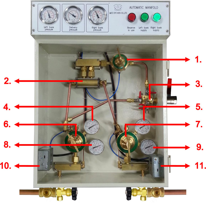
The gas supply that is in the supply of gas to the piping system is the "main supply end" and the spare end is the "secondary supply end". The gas is output from the cylinder, the check valve, the joint and the main switch valve enter the left and right input terminals of the control unit of the switch device, and then the main pressure regulator valve of the device is replaced. Each main regulator valve has a port mounting pressure gauge at the high pressure input to indicate the pressure value of the connector.
Oxygen, nitrous oxide, air, and carbon dioxide are automatically switched. The pressure regulator of the main regulator is set to 100 to 110 psig; nitrogen is 210 to 220 psig. The pressure settings of the two main pressure regulators in each automatic switching device are set to the same pressure value at the factory. In addition, there are two ports on the low pressure side of the main pressure regulating valve, and a pressure gauge is also installed on one port to indicate the pressure value of the low pressure output port.
The two inputs of the exchange valve are connected to the two main pressure regulators. The connected copper pipe and the exchange valve are connected by a one-way valve. This check valve is used to prevent gas from returning to the main regulator valve.
All safety relief valves are used to prevent over-pressure in the event of a failure of the main regulator and prevent intermediate control of the automatic switching device. When the gas supplied from the main gas supply end to the exchange valve of the switching device is lower than the preset pressure, the exchange valve will automatically switch the gas supply from the secondary gas supply end.
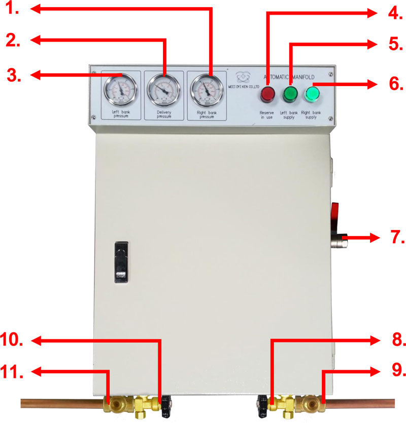
There are three pressure gauges in front of the box of the automatic gas switching device. The pressure gauge on the left indicates the pressure of the cylinder gas at the left gas supply side; the pressure gauge in the middle indicates the gas pressure output from the automatic switching device; the pressure gauge at the right indicates the pressure of the cylinder gas at the right gas supply side.
Three status indicators are also installed in front of the cabinet. When the pressure of the gas cylinders of the main gas supply side and the sub gas supply side is sufficient, the pressure switch causes the electronic circuit to light its one side of the green light (indicating that the side is the main gas supply side). When the pressure is reduced to the preset pressure, the pressure switch extinguishes the original bright green light and the other green light; simultaneously sends an alarm signal to the remote alarm.
When the gas at the right end of the main air supply end is depleted, the pressure provided by the right main pressure regulator of the automatic switching device also decreases. Therefore, when the gas pressure at the right gas supply side drops below 100 psig, the pressure switch will be activated to cause the red indicator light to turn on and the original bright green light will also be extinguished. When the gas cylinder of the right gas supply side is filled again, the red indicator light goes out and is in standby state, the remote alarm system returns to normal state, and the original main gas supply end (right gas source end) becomes the secondary gas supply end. The secondary gas supply (left gas source) becomes the main gas supply.
The pressure gauge and light display reminds the user to replace the depleted cylinder. And the remote alarm system can be connected to the printed circuit board of the control unit.
The gas supply that is in the supply of gas to the piping system is the "main supply end" and the spare end is the "secondary supply end". The gas is output from the cylinder, the check valve, the joint and the main switch valve enter the left and right input terminals of the control unit of the switch device, and then the main pressure regulator valve of the device is replaced. Each main regulator valve has a port mounting pressure gauge at the high pressure input to indicate the pressure value of the connector.
Oxygen, nitrous oxide, air, and carbon dioxide are automatically switched. The pressure regulator of the main regulator is set to 100 to 110 psig; nitrogen is 210 to 220 psig. The pressure settings of the two main pressure regulators in each automatic switching device are set to the same pressure value at the factory. In addition, there are two ports on the low pressure side of the main pressure regulating valve, and a pressure gauge is also installed on one port to indicate the pressure value of the low pressure output port.
The two inputs of the exchange valve are connected to the two main pressure regulators. The connected copper pipe and the exchange valve are connected by a one-way valve. This check valve is used to prevent gas from returning to the main regulator valve.
All safety relief valves are used to prevent over-pressure in the event of a failure of the main regulator and prevent intermediate control of the automatic switching device. When the gas supplied from the main gas supply end to the exchange valve of the switching device is lower than the preset pressure, the exchange valve will automatically switch the gas supply from the secondary gas supply end.
There are three pressure gauges in front of the box of the automatic gas switching device. The pressure gauge on the left indicates the pressure of the cylinder gas at the left gas supply side; the pressure gauge in the middle indicates the gas pressure output from the automatic switching device; the pressure gauge at the right indicates the pressure of the cylinder gas at the right gas supply side.
Three status indicators are also installed in front of the cabinet. When the pressure of the gas cylinders of the main gas supply side and the sub gas supply side is sufficient, the pressure switch causes the electronic circuit to light its one side of the green light (indicating that the side is the main gas supply side). When the pressure is reduced to the preset pressure, the pressure switch extinguishes the original bright green light and the other green light; simultaneously sends an alarm signal to the remote alarm.
When the gas at the right end of the main air supply end is depleted, the pressure provided by the right main pressure regulator of the automatic switching device also decreases. Therefore, when the gas pressure at the right gas supply side drops below 100 psig, the pressure switch will be activated to cause the red indicator light to turn on and the original bright green light will also be extinguished. When the gas cylinder of the right gas supply side is filled again, the red indicator light goes out and is in standby state, the remote alarm system returns to normal state, and the original main gas supply end (right gas source end) becomes the secondary gas supply end. The secondary gas supply (left gas source) becomes the main gas supply.